
AGMA Member CompanySince 1946East Walpole, MA
GEAR DESIGN & MANUFACTURING REFERENCE LIBRARY
Reference information for gear geometry, gear calculations, splines, symbols, formulas and inspection procedures — supported by decades of practical gear manufacturing experience.
We provide technical resources to help designers, engineers, purchasing teams and maintenance professionals review common gear and spline terminology, dimensional relationships and manufacturing considerations before a component reaches production.
Use them to support preliminary design work, interpret existing drawings, prepare manufacturing specifications or better understand how gear features are measured and inspected.
Quick Gear Calculator
Spur & helical · diametral pitch · full-depth involute
Reference values only — validate application-specific dimensions, loads, fits and tolerances before final design release.
Resource library includes
Important: These resources are provided as reference information to help conceptualize a design. Application-specific dimensions, loads, fits, tolerances, materials and operating requirements should be independently validated before final design release.
Gear formulas & dimensional references
Gear drawings contain a connected set of dimensions and tooth-geometry values. Our reference materials give convenient access to commonly used relationships for spur, helical and worm gearing, along with a consolidated guide to gear symbols and terminology.
Resource · Spur gears
Use this reference when working with common spur gear dimensions and diametral-pitch relationships.
Relationships covered
Useful for: preliminary spur gear calculations, reviewing existing gear dimensions, interpreting prints and preparing specifications for custom spur gear manufacturing.
Resource · Helical gears
Helical gearing introduces relationships between the normal and transverse planes in addition to the basic dimensions used for spur gearing.
Use this information when reviewing the geometry on a helical gear drawing or determining how specified values relate to one another.
Formulas & rules involving
Useful for: helical gear calculations, print review, dimensional reference and preparation for custom helical gear manufacturing.
Resource · Worm gears
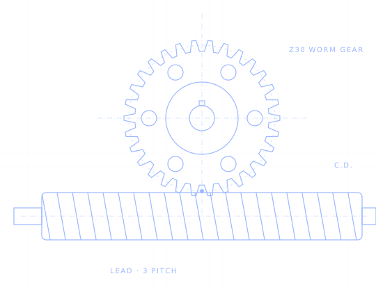
Worm and worm-gear sets require the geometry of two mating components to work together. This reference provides calculation information for common worm and worm-gear dimensional relationships.
For manufacturing or inspection of an existing worm set, information for both mating components helps establish the intended center distance, fit and operating relationship.
Useful for: worm gear calculations, worm-and-gear drawing review, mating-component specifications and manufacturing preparation.
Resource · Terminology
Technical drawings and gear formulas frequently rely on abbreviated symbols. This reference provides a common terminology guide for values used throughout gear calculations and inspection.
Use it alongside the spur, helical, worm and inspection resources when interpreting formulas or preparing manufacturing documentation.
Gear geometry
Gear quality & inspection
Spline & serration references
Spline specifications require more than a tooth count. Fit, tooth form, diameters and the relationship between the internal and external components all affect how a spline interfaces with its mating part.
We provide separate references for parallel-key splines and for involute splines and serrations.
Resource · Straight-sided splines
Use this resource when reviewing dimensional and fit information for standard parallel-key spline configurations — comparing spline dimensions and fit conditions used with straight-sided spline connections.
When requesting manufacturing, identify the applicable spline specification and fit rather than relying on a nominal diameter alone.
Useful for: straight-sided spline reference, spline fit review, shaft and bore specifications and preparation of internal or external spline drawings.
Resource · Involute splines
Dimensional relationships for 30° pressure-angle involute splines and serrations — letting designers work between known tooth counts and specified diameters when reviewing basic involute spline geometry.
We manufacture both internal and external splines, including involute and straight-sided configurations.
Calculations involving
Useful for: involute spline calculations, serration reference, spline print review and internal/external spline manufacturing preparation.
A spline that appears dimensionally similar may not be functionally interchangeable with another spline. Fit definition is especially important.
For a manufacturing review, provide
Gear inspection reference
Design data becomes meaningful in production only when the specified features can be measured and verified.
Our Inspection & Testing Procedures resource documents general inspection methods across many gear and power-transmission components. For new jobs, we develop a quality plan tailored to your part, drawing and purchase-order requirements.
| Component | Documented inspection considerations |
|---|---|
| Spur Gears | Measurement over pins, tooth-to-tooth error, total indicated runout, total composite variation and center-distance/backlash checks |
| Helical Gears | Measurement over pins, whole depth, lead, mating-part center distance, backlash, tooth bearing and runout |
| Internal Spur Gears | Internal measurement over pins, dimensional checks, runout and gauge-based checks where applicable |
| Bevel & Miter Gears | Addendum, tooth thickness, tooth depth, radial and axial runout, tooth bearing, toe/heel/cross bearing and backlash at the required mounting distance |
| Worms | Measurement over pins, runout, whole depth, center distance with mating component, tooth bearing, lead, addendum and tooth thickness |
| Worm Gears | Measurement over balls where applicable, throat diameter, backlash with the mating component and bearing roll testing |
| Sprockets | Measurement over pins, circular-pitch testing using sample chain and runout |
| Ratchets | Runout, tooth-profile angle, tooth-top width where specified and tooth position relative to the bore |
| Racks | Measurement over pins at multiple locations, circular pitch and straightness after gear cutting |
| Straight-Sided Splines | Root diameter, tooth thickness, runout and fit checks with a gauge or mating component according to class |
| Involute Splines | Measurement over pins, runout and fit checks using gauges or a mating component according to class |
Depending on the drawing or purchase-order requirements, additional tooth-element verification such as lead, profile and spacing may also be required.
Mating components
Some gear characteristics are best evaluated as part of the intended operating relationship rather than as isolated dimensions.
Helical gears, worm sets, bevel gears and splines may require information about — or access to — the mating component to evaluate center distance, backlash, tooth bearing or fit.
When a mating gear, shaft, spline, worm or other component controls the functional relationship, include that information with your drawing or quote request whenever possible.
From engineering data to the shop floor
The reference documents on this page help organize design information — but manufacturing begins with a clearly defined customer specification.
When requesting a quote or manufacturing review, provide the information that applies to your component.
Tick what you already have — the meters show how complete your specification is.
Include the component type and applicable tooth data:
Define the features surrounding the gear teeth:
Specify, where required:
Include:
Include a PDF drawing, print, CAD file or other controlling specification whenever available. Clearly identify revisions and any dimensions or requirements that are critical to the application.
Investigating an existing component because of fit, noise, binding, wear or another performance issue? Provide the available mating components and original drawings when possible.
Custom gear manufacturing support
We have manufactured custom gears and power-transmission components since 1946, supporting OEM and MRO requirements with custom gear cutting, CNC machining and dedicated gear inspection.
The resources on this page connect directly to what we manufacture:
Specialized gear hobbing, shaping, bevel generation, rack gearing, thread milling and involute gear milling — supported by CNC turning and milling for related component features — plus dedicated gear inspection for profile, lead, composite characteristics and other dimensional and functional checks.
With 120+ years of combined industry experience, our team reviews manufacturing requirements and helps identify the information needed to move a defined component from drawing to production. We follow ISO-aligned quality practices, produce to AGMA standards as required, and support both OEM production and MRO replacement requirements.
1946
Manufacturing custom gears and power-transmission components since
120+
Years of combined industry experience
ISO
Aligned quality practices
AGMA
Standards as required · AGMA member